Imaging Ellipsometers inherit the measurement principles of conventional ellipsometers: They measure the sample-induced change of polarization of the probing beam. This change is cast into two real numbers per probing photon energy, the so-called ellipsometric parameters Δ (“Delta”) and Ψ (“Psi”). By means of computational sample modelling, these parameters translate into the sample properties of interest, e.g. one or more layer thickness(es), refractive index and/or absorption.
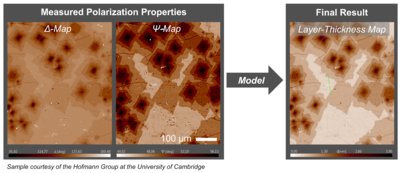
In contrast to conventional ellipsometers, however, imaging ellipsometers acquire stacks of microscope images (rather than “just” intensity values) while modulating the probing polarization state and/or the polarization analyzer (polarization modulation). Each pixel of the camera acts as an individual photo detector, which results in more than 500 000 intensity curves measured in parallel. Each pixel of the microscope image then returns a measured value of Δ and Ψ, which form the so-called Δ-Ψ-maps. Hence, the computational modelling now provides a pixel wise translation of the Δ-Ψ-maps into spatially resolved micrographs of the model fit results, in particular thickness maps and/or refractive-index maps (Fig.1).
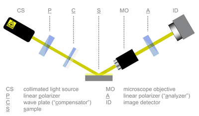
Accurion’s Imaging Ellipsometers apply the so-called PCSA design (polarizer, compensator, sample, analyzer): The polarization control (or polarization state generator, PSG) comprises a linear polarizer and a waveplate (“compensator”) for phase retardation. The polarization analyzer (or polarization state analyzer, PSA), which is located between the microscope objective and the image detector, comprises just a sole linear polarizer (Fig.2).
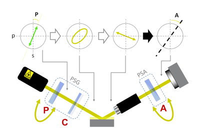
The three polarizing components (P, C, A) are mounted on motorized hollow-shaft rotators for the polarization modulation. Accurion’s Imaging Ellipsometers apply the methods of nulling ellipsometry and rotating compensator ellipsometry. In both cases, every pixel of the acquired image stack yields an intensity curve as a function of the applied P-, C- and A-rotation angles settings:
- Nulling Ellipsometry (NE): The nulling mode iteratively rotates the polarizer (P) and the analyzer (A) to detect the angular positions of relative intensity minima in order to calculate Δ and Ψ (Fig.3). This is the most accurate of all ellipsometry modes and is especially useful for detecting extremely small variations of the refractive index and/or the layer thickness (e.g. mono-atomic or monomolecular layer steps).
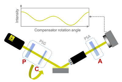
- Rotating Compensator Ellipsometry (RCE): RCE measures the camera signal as a function of the compensator rotation angle (Fig.4). It is one of the most common ellipsometry modes on the market as it allows for fast measurements on all types of samples.
It is an outstanding feature of Accurion’s Imaging Ellipsometers to provide these complementary ellipsometry modes in a single instrument.


